Here I present a small composition of some
classical (and by me build and more established) circuits:
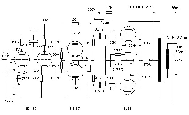
Power amplifier with 2 x EL34 in Gegentakt A/B with approx. 35 W
achievement. Data and attitudes lt. Telefunken laboratory book 1966. (NB.
Fundamental it applies that indicated performance data of the amplifiers can be
achieved only with stable supply voltages, - however in addition later under
power packs)
Classical circuit with preamplifier, Phasenumkehrung and Driver,
all stages with cathode inverse feedback as well as DC voltage inverse feedback.
Ausgangstrafo of company HSGM angel Trafo (www.hsgm.com,
then on the German side go!). - The preamplifier tubes can be exchanged by 5814,
E82CC, 6SN7, L63 o.a.
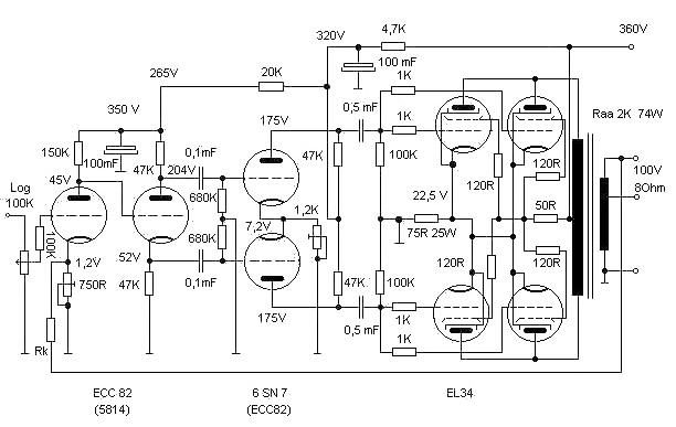
The next amplifier is a 75-Watt-Verstärker with 4 x EL 34.
The power pack for this should be brutally hard, however the output stage draws
400 mA. I hab' always the 866 rectifier valves taken, thus Hg gas, 2 min heat is
mandatory, then over relays the mass up of the anode coil connect. 800 mA supply
the 866, if Ueff Trafo smaller 1000 V. - Please consider, urgently: If an Hg gas
tube first is time close-set, it should become about approx. 20 minutes
pre-heated, - without anode voltage! - with it mercury decently evaporates,
afterwards these must become pre-heated only still approx. one until two
minutes.
Power pack:
All indicated performance data of power amplifiers can be reached
only by hard and stable supply voltages. The Trafo should have 20% power
reserve. As electric rectifiers all appropriate tubes are suitable, one should
however internal resistances with the Trafoberechnung consider. With A or A/B
amplifiers, see above, is a vacuum rectifier valve of already ok, but please
consider the fact that an Stereo amplifier its 400 mA anode current to here
already have wants, here would be applicable with single power pack only the EZ
150 - however who has those already. Thus silicon diodes, because inexpensive!
One of me preferred alternative (for purely aesthetic reasons and
because I got here from the Americans it in Italy times inexpensive) are gas
electric rectifiers, here in this case took I the 866, (mercury filling), with
anode voltages under 1000 V can one calms down 800 mA to infer (indication:
Raytheon). Blue shining after 1 min. warm up period (mandatorily, otherwise
heating spiral poisoning!!!) sees simply good out (a Macke has everyone!).
Advantage: Voltage drop only max.15 V, independently of the load. Who builds
amplifiers in class B, only silicon diodes or GAS ELECTRIC RECTIFIER should use!
The spontaneous increase of the anode current with strong signals
lets the tension drop with vacuum electric rectifiers too strongly, this applies
in particular with Pentoden for the g2-Spannung. - It is one inserts monster
Elkos, over then the rectifier valves when switching on on to overloads (one
should take only the capacity those is really necessary!). From applications of
the relevant industry it is well-known that Elkos are to be switched however
with appropriate metallized paper capacitors paralell. Proven, also from the
circuit history of the 40-Jahre until today is: Tube - MP (16-32 µF) -
throttle - Elko (50-100µF), in particular with push-pull circuits hands a
small Elko, there humming compensation in the Ausgangstrafo.
The preliminary stages can be sieved then after desire and mood.
Usual gas electric rectifiers are 83, 816, 866, AX1, AX50 etc. usual vacuum
electric rectifiers GZ 32, GZ 34, 5Z3, 5U4 and each quantity other one.
Again to the elucidation: The data published in the relevant
laboratory books of the manufacturing firms (by the technical literature) were
then taken over to refer to absolutely durable supply voltages (at Telefunken
one worked with large battery sets), already Philips gave itself these data 1941
under this restriction, likewise Valvo and GEC.
Rule of thumb: If the tension is soft, the operating point
shifts with strong signals, from this arises then less achievement and higher
distortion factor.
A word to the Ausgangstrafo. Its impedance (Raa) must tune, also
the anode current preloading, and one does not need expensive Tango, in order to
obtain good results.
Good results hang off from correct and clean wiring, correct mass
of the individual stages (loops avoid), a good and sturdy steel sheet chassis
(magnetic shielding), a good entrance potentiometer and good passive
construction units (however please do not exaggerate).
Same applies to resistances, to the R´s lying in NF-circles
already is metal film resistors for o.k. - for all other rich normal.
Who likes it at home more quietly - here small headphone
amplifier, also this is already well-known since the 50-Jahren. It is a double
cathode Follower with the 12B4A, entrance into cascode circuit. Functioned great
and frequency response like you want and without end. Actually as LINE amplifier
one used. Functioned with each headphone and you can even also times your 8 ohm
boxes attach, - the rendition is quietly however highly transparent. I operate
it for now 10 years with different headphones. The reference in the circuit
“if necessary” meant, one can insert the inverse feedback (with that 2.2
kOhm resistance) or also not - its influence is very small.
The power pack for the headphone amplifier is uncritical, I 83
used as rectifier valve and then the proven throttle sieving made. In the case
of use my Yamaha headphone hears one neither noise nor hums.
Here an intermediate text of me (Jogi): Since I also
build myself this mad headphone amplifier, I left myself the transformer
meanwhile from a friend winding. - Here the Trafodaten, which I would naturally
not like to withhold from you:
A core M85a is used.
Primely. 235 V = 1045 Wdg. 0.35 Cul.
Sec. 260 V - 0.2 A = 1270 Wdg. 0.30 Cul
Sec. 6.3 V - 3.0 Amp = 31 Wdg. 1.10 Cul.
This Trafo on bridge rectification is laid out, not
with a rectifier valve - the nuclear size M85a is enough well, but,
nevertheless, to just apply out in order the necessities 3 ampere of the tube
heaters. In the case of use of a rectifier valve the additional filament current
need would be too largely, one would have a M85b-Kern to use - optically much
too large for this amplifier. The Trafo computed here lies still scarcely in the
“green range”, optically regarded.
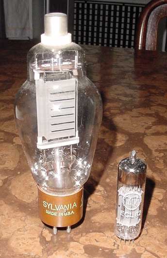
And here still another small contribution to the unsurpassed
“KAWUMM” - Endröhre, the famose EL 156 of Telefunken. It is from the
achievement clearly more strongly than the KT 88, their energy dissipation
during automatic bias is 50 Watts (!) with 800 V-anode voltage, but it a Exot on
the market and around a multiple is more expensive. It was developed actually
for the medical-technical range, applied however already soon its in modulators
for transmitters and in large public-address systems. In Gegentakt B-circuit
loosely 130 Watts come out, with 4 Endröhren in Gegentakt A/B already times
160 Watts, but those come then more absolutsauber. So which one does not need at
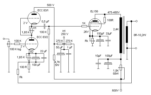
home necessarily, therefore here the diagram in Gegentakt triodes circuit:
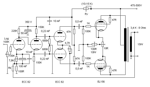
Actually the Ausgangstrafo for Raa = 2.8 must be kOhm, here
functioned in addition, outstanding the over adjustment. As one white sinks with
triodes then power output, in addition, the distortion factor. Power output lies
here with approx. 25 W, but with smallest distortion factor and a clear and warm
sound (that is naturally my subjective opinion), - my friends maintain, this
circuit with this tube would sound better than with the 300B (meinerseits no
comment!).
I can say only modestly: with the correct loudspeakers the
amplifier sounds really well, particularly with classical music. The
Ausgangstrafo is inexpensive Angel Trafo (I want to make no advertisement here,
but relatively few cost her and work very well and who wants to dissipate money
already unnecessarily!).
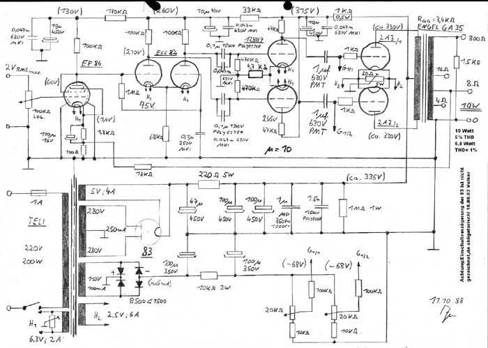
Here now a connection diagram for SE amplifiers indicated as
EL156 in triode circuit, power output 10 Watts for Ra= 2.4 kOhm and tensions.
(Computation of the operating point with the help of the diagrams, Telefunken
laboratory book 1966)
Entrance into cascode circuit with maximum utilization of the
ECC83, attainable reinforcement factor µ= 70 (about!). Characteristic: 2.
Heating circle for obenliegende triode with central tapping and connection with
250 V= for compensation of the tension potential Ufk between heater element and
cathode. - Whistles otherwise immediately through!
With exchange with other tubes absolutely permissible Ufk
consider and if necessary heater element “artificially high-put”. (Example:
ECC83 Ufk permissible =180 volt). To connection see marking H1.
The anode voltage does not have to be 600 V. It is because of
which I only this Netztrafo had. The 1,5K 50W resistance should be replaced then
by 10 a Hy-throttle (anode current load to consider!). Rk is a potentiometer 300
ohms of 20 W.
The Ausgangstrafo was an old however good Chicago Trasformer with
50 W-achievement and 160 mA max. anode current (year of construction 1955).
The power pack brings correctly power, due to which Trafospannung
became effective 482 V security the 866 assigned, the Trafos is from old radar
consoles of the US-Army developed (make HEWLETT-PACKARD) and hochspannungsfest
poured - as said, I had only this….
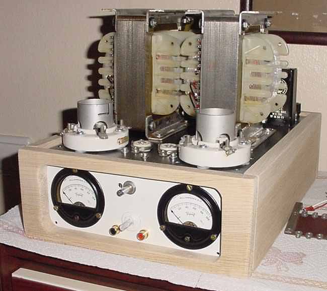
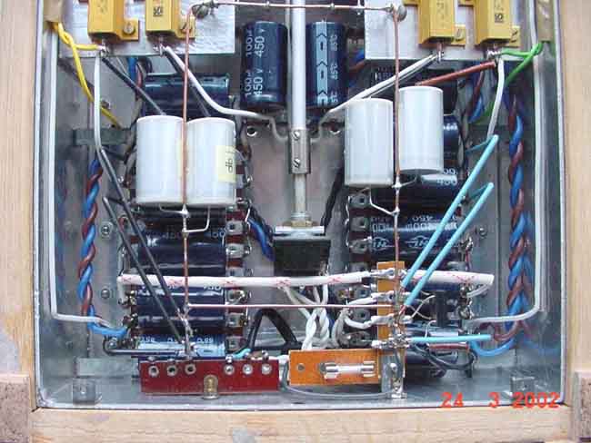
In the following the diagram of the power pack, a throttle
sieving is of advantage absolute with smaller tensions (e.g. lp 220 of Buerklin
or angels).
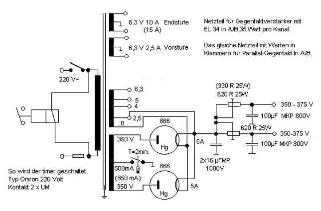
The timer is a standard industrial part and can either with
R-S-Components or with Schuricht be bought. There are it like sand at the sea, I
calls here only times three manufacturers: Omron, Finder, Mitsubishi. They are
offered including bases. There is miniature parts with internal reed contacts,
usually 250 V - 1 A load. Therefore the timer must lie in the earth line of the
Trafos, because the switching potential goes there against zero. - Are no fear,
this Dinger very durably and reliably, mine functioned already for 10 years
without disturbance. The approximate dimensions - without bases - are 20 x 20 x
60 mm, with adjusting potentiometers at the head and 2 control LED. There are it
for max. 30 seconds, 1min, 3min, 10min, 30min etc. etc. etc., - as said in
infinite remarks and designs. They cost, depending upon design and manufacturer,
approximately between 30 - 80 DM.
I use this power pack as standard for all my amplifiers. The
advantage of the Gasröhren is independent the constant voltage drop of
approx. 15 V, of the load.
Against different opinions do not cause the Hg electric
rectifiers disturbances with the anode voltages very low for it, those notice
that not at all - they supply high rivers with large reserve to stop with with
impulse load (ca.2, ä max). - In addition they are to be looked at very
beautifully in an amplifier.
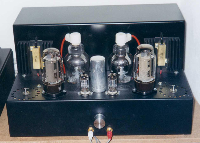
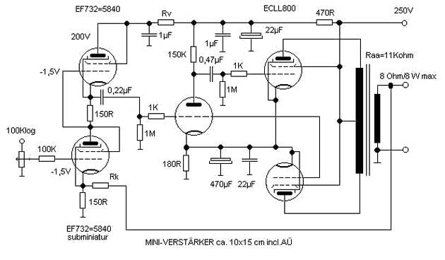
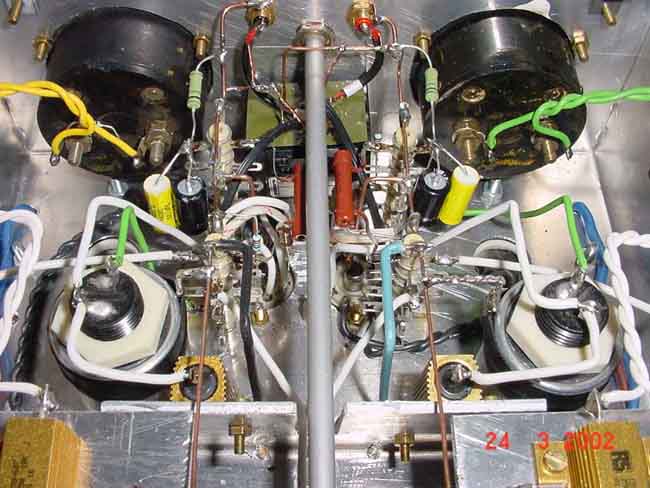
When I had recently something time and leisure, I tinkered myself
the following mini Amp with 2 x 8 W achievement together. In Stereoausführung,
without power pack, one gets this mini amplifier on a surface area of 10 x 15 cm
under I him on a piece of Pertinax had set, sheet metal drum around etc. ......
and had funzt! One can put the whole thing easily into the brief case and has
still place for the breakfast box. - would have to be able to build one actually
also into a breakfast box completely, that is still another idea…
The resistance check valve is (at short notice) a 3,3-kOhm-Potie,
with it a tension by 200 V is adjusted. If the resistance value is determined, a
fixed resistor with appropriate value should be used.
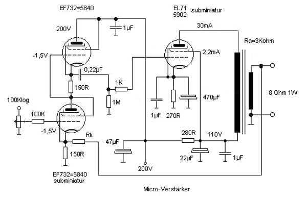
In order to be able to convert the idea with the breakfast box, I
made the mini Amp smaller still whole enormously, now he (nearly) can even with
batteries is operated…
The EL71 is, exactly like the preliminary stage tubes of both
mini amplifiers, a sub-micro tube with long soldering connection. With Singer
(Helmut Singer electronics, Feldchen 16-24, 52070 Aachen, Tel. 0241-155315) hab'
I the 5902 = EL71 found, the EF 732 = 5840 gibt's evtll. with Heinze + Bolek.
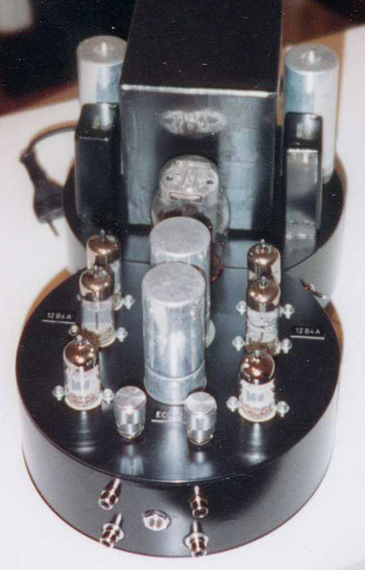
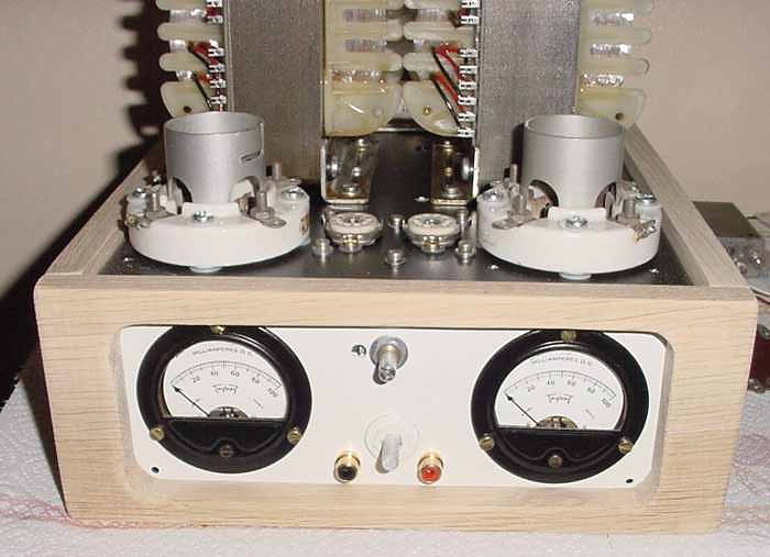
The newest Project of peoples is an amplifier which one only as
mallet arcose for the neighbours designate can. One recognizes the sweet, small
Endröhre in the following photo. :
 It is 812 A, as Treiberröhre uses peoples the ECL 82. Here
the diagram is in addition:
It is 812 A, as Treiberröhre uses peoples the ECL 82. Here
the diagram is in addition:
 - and here the Netztrafo and the output transformer, as it is
manufactured after Volkers computations by Trafo Baule:
- and here the Netztrafo and the output transformer, as it is
manufactured after Volkers computations by Trafo Baule:
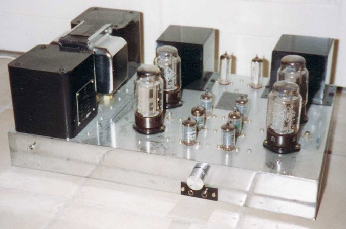
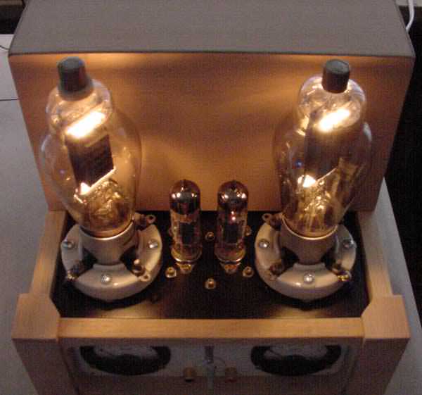
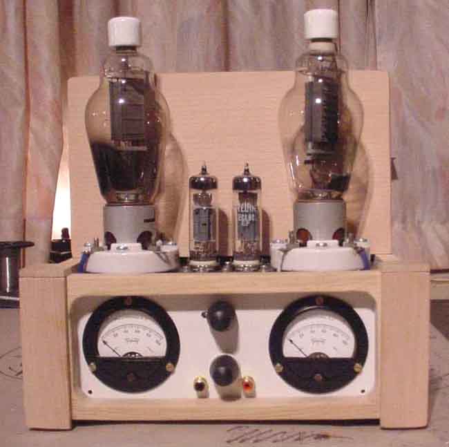
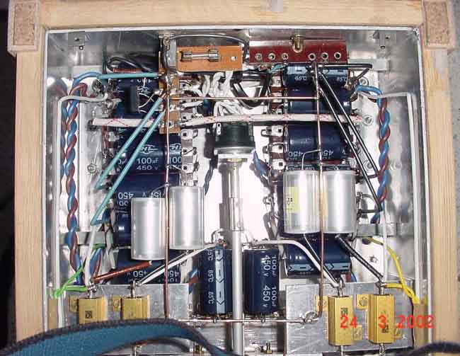
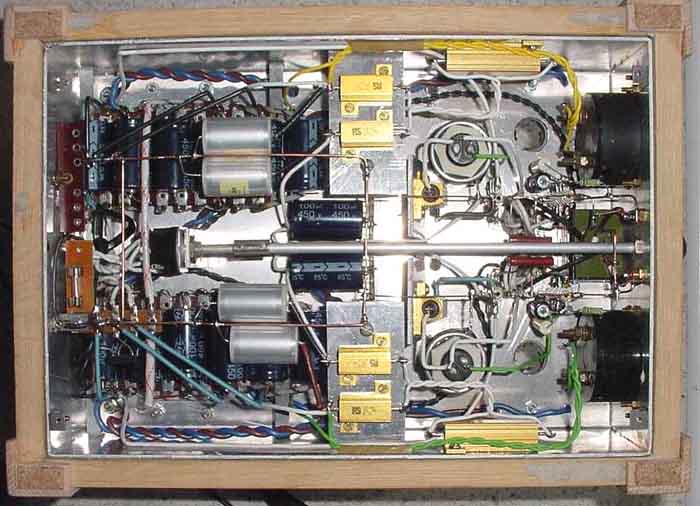
 Further photos of the finished amplifier:


In the course of the development its transmission triode
amplifier sent me peoples “grease” from the driver circuit modified triode
output stage. Peoples wrote in addition:
“the driver my 838 amps is already smaller for itself more
purely triodenamp! with 2 A 5 dollar the piece roar build themselves one thereby
one superamp. and there the circuit in loftin did not white is is also the
distortion zero, kopplungsglieder in the transmission path. greeting of
peoples”
- Here the circuit:
The still following wrote me peoples in addition:
The idea for this Amp actually begins with the T40-Triodenamp of
the Ralf Suertenich. Its idea this tube was to be used, there it a double triode
looked for with 2 different systems: 1 system for the preamplification and 1
system as strong Endtriode.
These tubes gives it in the States in very many different types
and comes from application in television sets.
Its choice fell on the 6EA7/6EM7, since it is a beautiful octal
base type, easily and cheaply available is, the price lies in such a way around
4-9 euro per unit, NOS-NIB. There are also still different octal types with
similar data, but remain we times with this: 1. System has µ = 64 and 2.
System, the 10 Watt triode, µ ~ of 5.
The circuit was actually meant as drivers with Trafokopplung for
transmission triodes: Over ouple ko´s to save we computed in loftin white
- and let us see there, in Ralf´s amplifier funzt that extremely cleanly,
the part marched like a one and deliver approx. 1.2 Watts of achievement
distortion-free.
With my 838 Amp I need more power reserve and after so some
counting and circling evaluate found I an attitude, where the Endtriode
nevertheless delivers 1.9 Watts undistorted with approx. 6 Watts of energy
dissipation. I computed then in addition still the RA of the outer one - and a
small pure Triodenamp was there born.
Who white not in loftin to build wants, can him also with
Koppelko´s build; but the power pack does not become simpler thereby,
because the Endtriode works with a lower anode voltage than the preliminary
stage (see diagram) at simultaneous enormously more power demand. There one must
fiddle then with the power pack, possibly 2 coils for Ua and 2 rectifier valves.
So, developed, one needs originals 2 amplifier tubes and 1
electric rectifier. - Thus a really small part.
Greeting of peoples.
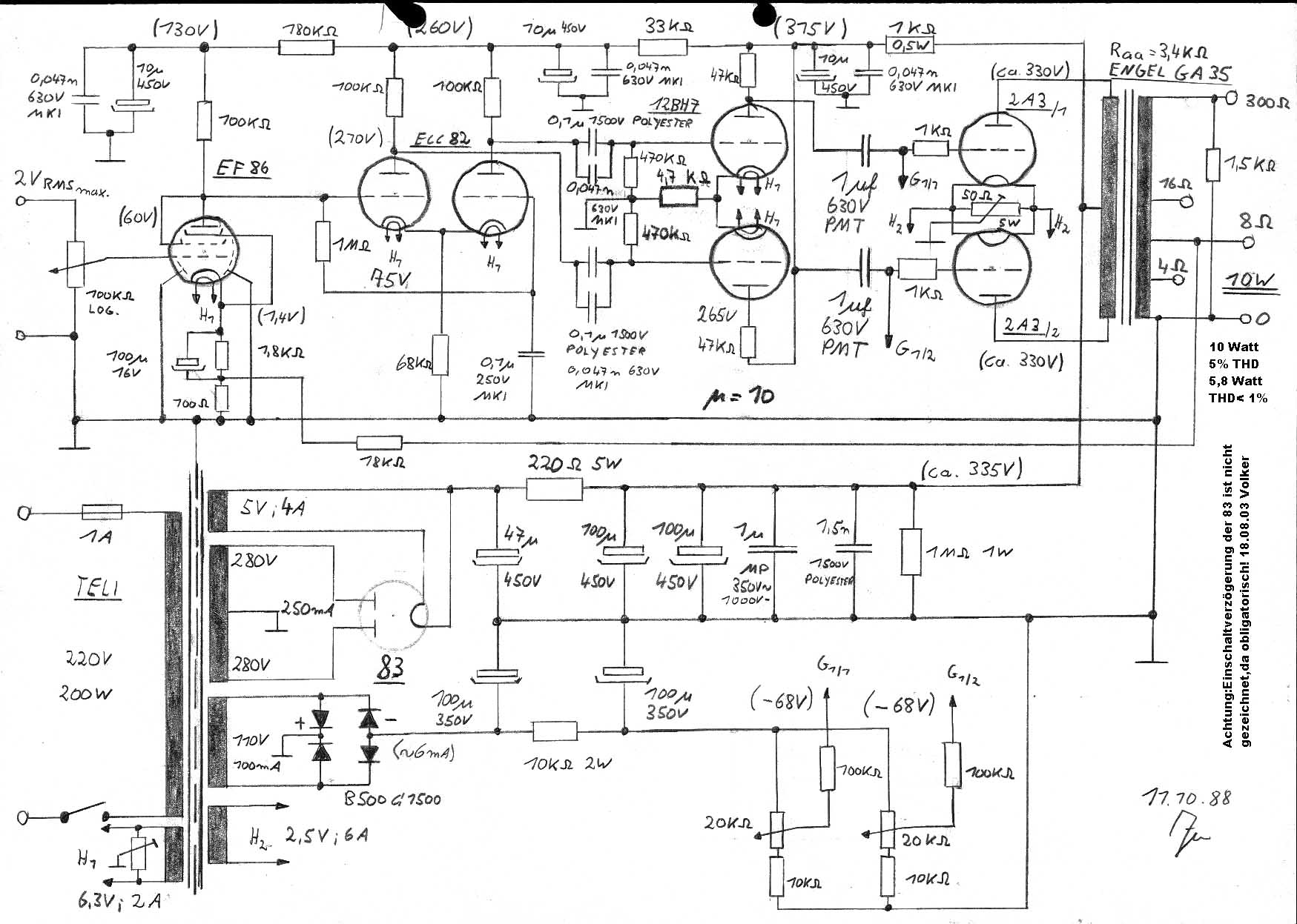
The following diagram shows a PP-Amp with the 2A3:
 (With the mouse button the picture click, it then
in full dissolution one represents.)
(With the mouse button the picture click, it then
in full dissolution one represents.)